Section 10: Lab 4B Head Start
In the previous discussion, you learned how to use the processor functional-level model (ISA simulator) to execute assembly programs. In Lab 4A, you implemented the processor components you will need to implement your single-cycle processor. In this discussion, you will leveraged what your prior work to write an initial directed assembly test for the ADDI, ADD, and MUL instruction. We provide you a simple single-cycle processor that supports the ADDI and ADD instructions, so you will then incrementally add support for the MUL instruction. Remember the TinyRV1 ISA manual is located here:
1. Logging Into ecelinux with VS Code
We have drastically simplified the process of logging into ecelinux
with VS Code using the workstations. Find a free workstation and log into
the workstation using your NetID and standard NetID password. Then
complete the following steps:
- Open the ECE 2300 folder on the desktop to locate two shortcuts
- ECE 2300 Handouts: opens the handouts page
- ECE 2300 VS Code: starts VS Code (enter server number and password)
That is it! Our custom ECE 2300 VS Code script will take care of:
- installing Remote SSH, Verilog HDL, Surfer extensions
- configuring SSH for accessing
ecelinuxwithout extra prompts - starting VS Code connected to
ecelinuxwithout extra prompts - opening the file explorer in your
${HOME}/ece2300directory - installing the Verilog HDL extension on the server
- opening a terminal
We are not using a discussion repo today, instead you will be working in a copy of your group repo.
% source setup-ece2300.sh
% cd ${HOME}/ece2300
% git clone git@github.com:cornell-ece2300/groupXX sec10
% cd sec10
% git remote remove origin
where XX is your group number. Go ahead and do a clean build.
To make it easier to cut-and-paste commands from this handout onto the
command line, you can tell Bash to ignore the % character using the
following command:
Now you can cut-and-paste a sequence of commands from this tutorial
document and Bash will not get confused by the % character which begins
each line.
Throughout this handout you will see discussion check-off tasks. The TAs will not be assessing your understanding. Instead, students should show their work to another student and then together they will perform a self and peer assessment of each discussion check-off task. The student peer will initial the check-off. As always, the assesssment should based on the demonstrated understanding using our five-point scale as follows:
-
5 (Mastery): Student mastered the check-off without any help and feels very confident in their understanding; student could teach other students about the corresponding concepts
-
4 (Accomplished): Student accomplished the check-off with maybe a little help and feels good about their understanding, but could probably use a little more time to really master their understanding; student is probably not quite ready to teach other students about the corresponding concepts
-
3 (Progressing): Student completed the check-off but needed significant help; student is not quite confident in their understanding and needs more time to really improve their understanding of the corresponding concepts
-
2 (Beginning): Student started but did not finish the check-off
The goal is not for one student to judge another student, but for the two students to agree on the demonstrated level of understanding. There is nothing wrong with agreeing on a 4 or 3. This can help a student crystallize where they should focus their time to improve the understanding!
Near the end of the discussion section, the student should raise their hand and show their overall progress to a TA who will initial and collect the check-off sheet.
Discussion section check-off sheets are not graded!
Unlike the lab check-off sheets, the discussion check-off sheets are not graded. They will not impact your grade in the course in any way. The discussion check-off sheets provide formative self and peer assessment. They enable students to gauge their progress in mastering the concepts presented in the discussion section, and enable the instructors to get an overall feel for how the class is doing. Please make sure your self and peer assessments are honest and accurate!
Discussion Check-Off Task 1: Verify Initial Release
We always start by running make check to get a high-level view of
what is and is not working. So go ahead and do make check again and
look closely at what tests are passing and what tests are failing.
Show a peer student the result of make check. Work together to
conduct a self and peer assessment and have the peer student initial
the check-off.
2. Simple Single-Cycle RTL Processor
We provide you a simple single-cycle RTL processor which supports the ADDI and ADD instructions. Spend a few minutes looking at the Verilog for the provided datapath.
The provided Verilog implements the following block diagram. Carefully compare the Verilog code and the block diagram to understand the one-to-one mapping.
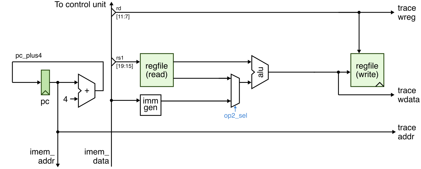
Notice that one difference from lecture, is that the single-cycle processor used in the lab includes a trace interface. The trace interface is used for verification and should produce a "trace" of all instructions executed by the processor. This interface is an important practical aspect of implementing a real processor. We need a simple way to check that each instruction has executed correctly.
Whenever the processor executes an instruction it should set the
trace_val output high. It should also set the trace_pc output port to
the PC of the executed instruction. If the instruction writes the
register file, it should set trace_wen to one, trace_wreg to the
corresponding write destination register, and trace_data to the data
written to the register file. If the instruction writes x0 then
trace_wen should be one, trace_wreg should be zero, and trace_data
is undefined. We will be able to write test cases that check the trace
interface to verify the processor is executing a given assembly program
correctly.
Now spend some time looking at the Verilog for the provided control unit.
The control signal table for this initial processor is shown below.
  // Localparams for op2_sel control signal

  localparam rf  = 1'd0;
  localparam imm = 1'd1;

  // Task for setting control signals

  task automatic cs
  (
    input logic op2_sel_
  );
    op2_sel = op2_sel_;
  endtask

  // Control signal table

  always_comb begin
    casez ( inst )
                          //  op2
                          //  sel
      `TINYRV1_INST_ADDI: cs( imm );
      `TINYRV1_INST_ADD:  cs( rf  );
      default:            cs( 'x  );
    endcase
  end
A control signal table has a column for every control signal and a row
for every instruction. Since the initial implementation only supports two
instructions, the initial control signal table only has two rows. The
first row has all of the control signals required to execute the ADDI
instruction, and the second row has all of the control signals required
to execute the ADD instruction. We are using a casez because we want to
support don't cares in the instruction decoding (i.e., see
TINYRV1_INST_ADDI in tinyrv1.v). In this case, we only need one
column since we currently only have a single control signal: op2_sel
which controls the mux for operand 2 of the ALU. Notice how we are using
a SystemVerilog task to set the control signals. This will make it easy
to add more columns in a clean way. Also notice how we have created
localparams (i.e., rf, imm) for the two values of the mux select.
These localparams can make your control signal table more readable.
Finally, take a look at the Verilog for composing the processor and datapath.
// Control Signals (Control Unit -> Datapath)

logic op2_sel;

// Status Signals (Datapath -> Control Unit)

logic [31:0] inst;

// Insantiate/Connect Datapath and Control Unit

ProcScycleDpath dpath
(
  .*
);

ProcScycleCtrl ctrl
(
  .*
);
Notice how it is using a new SystemVerilog .* operator. This operator
will automatically connect every port in the module to a wire with the
same name.
2. Directed Assembly Testing
Testing the processor is more complex than testing individual hardware blocks. We have provided you some testing infrastructure to simplify the process, but students should still expect to dedicated significant time to verifying their processor correctly implements the TinyRV1 ISA.
We have provided you a functional-level (FL) processor model (also called
an instruction set simulator) located in test/ProcFL.v. The FL
processor model executes the instruction semantics behaviorally using
high-level Verilog. It is not meant to model hardware. The FL processor
model can be used to make sure your tests are correct before you run
those tests on your single-cycle processor.
Here is a list of the test cases we will be working on today:
test/Proc-addi-test-cases.vtest/Proc-add-test-cases.vtest/Proc-mul-test-cases.v
Each file should only test a single type of instruction. Processor test cases look like this:
task test_case_1_basic();
  t.test_case_begin( "test_case_1_basic" );

  // Write assembly program into memory

  asm( 'h000, "addi x1, x0, 2" );
  asm( 'h004, "addi x2, x1, 2" );

  // Tell processor to start executing program

  go();

  // Check each executed instruction
  //           pc     en reg   data
  check_trace( 'h000, 1, 5'd1, 32'h0000_0002 ); // addi x1, x0, 2
  check_trace( 'h004, 1, 5'd2, 32'h0000_0004 ); // addi x2, x1, 2

  t.test_case_end();
endtask
Every processor test case includes three parts.
-
asmtasks are used to write instructions into the memory. Theasmtask takes two arguments: the address for the instruction and an assembly instruction represented as a string. Theasmtask will take care of converting the assembly instruction into a machine instruction. Theasmtasks represent the static instruction sequence (i.e., what instructions are stored in memory before the processor starts executing). The go signal is set to zero during this phase which means the wait inputs into the processor are one causing the processor to wait. -
gotask is used to tell the processor to start executing the program. -
check_tracetasks are like thechecktasks you have seen elsewhere, butcheck_tracetasks will wait for thetrace_valsignal to be high before checking to see if thetrace_addrandtrace_dataoutputs from the processor match the desired values. Thecheck_tracetasks are used to check the dynamic instruction sequence (i.e., what instructions the processor actually executes at runtime).
In this discussion, we will be adding one new directed test case for the ADDI, ADD, and MUL instruction. Obviously for the final lab submission you will need many more directed tests but this will be a good head start!
2.1. Testing the ADDI Instruction
Open up the test cases for the ADDI instruction.
We want to add a new directed test case which tests ADDI instructions where each instruction reads and writes the same register. Here is an example sequence of assembly instructions we can use for our test.
Go ahead and create a new test case called test_case_2_same_reg which uses
this asssembly sequence. You will need to use the asm task, the go
task, and the check_trace task. Be sure to add this test case to the
list of test cases in the main block at the bottom of the file.
Once you have finished writing a test case you should always test it on the FL processor first to ensure the test case is correct. Here is how to run just your new test case on the FL processor.
Verify that the test is indeed executing the expected instructions. Then run all of the ADDI test cases on the FL processor.
We provide you a simple single-cycle processor that supports the ADDI and ADD instruction, so let's try your new test case on the actual RTL implementation as well.
And let's zoom out to keep track of our progress.
Remember, you will need to add many more directed test cases for your final lab submission!
Discussion Check-Off Task 2: Verify ADDI Directed Test Case
Show a peer student your new directed test case. Then show the student the FL processor and the single-cycle RTL proceessor.
2.2. Testing the ADD Instruction
Open up the test cases for the ADD instruction.
We want to add a new directed test case which tests ADD instructions where each instruction reads and writes the same register. Here is an example sequence of assembly instructions we can use for our test.
Go ahead and create a new test case called test_case_2_same_reg which
uses this asssembly sequence. You will need to use the asm task, the
go task, and the check_trace task. Be sure to add this test case to
the list of test cases in the main block at the bottom of the file.
Once you have finished writing a test case you should always test it on the FL processor first to ensure the test case is correct. Here is how to run just your new test case on the FL processor.
Verify that the test is indeed executing the expected instructions. Then run all of the ADD test cases on the FL processor.
We provide you a simple single-cycle processor that supports the ADDI and ADD instruction, so let's try your new test case on the actual RTL implementation as well.
And let's zoom out to keep track of our progress.
Remember, you will need to add many more directed test cases for your final lab submission!
Discussion Check-Off Task 3: Verify ADD Directed Test Case
Show a peer student your new directed test case. Then show the student the FL processor and the single-cycle RTL proceessor.
2.3. Testing the MUL Instruction
We now want to add support for the MUL instruction to our single-cycle RTL processor. Let's follow a test-driven design approach, which means we should write the tests first before we implement the design. Open up the test cases for the MUL instruction.
We want to add a new directed test case which tests MUL instructions where each instruction reads and writes the same register. Here is an example sequence of assembly instructions we can use for our test.
Go ahead and create a new test case called test_case_2_same_reg which
uses this asssembly sequence. You will need to use the asm task, the
go task, and the check_trace task. Be sure to add this test case to
the list of test cases in the main block at the bottom of the file.
Once you have finished writing a test case you should always test it on the FL processor first to ensure the test case is correct. Here is how to run just your new test case on the FL processor.
Verify that the test is indeed executing the expected instructions. Then run all of the MUL test cases on the FL processor.
And let's zoom out to keep track of our progress.
Remember, you will need to add many more directed test cases for your final lab submission!
Discussion Check-Off Task 4: Verify MUL Directed Test Case
Show a peer student your new directed test case. Then show the student the FL processor and the single-cycle RTL proceessor.
3. Implementing the MUL Instruction
Now that we have written some test cases, let's go ahead and add support for the MUL instruction to the single-cycle RTL processor. We will use a seven step process:
- Step 1: Modify the datapath
- Step 2: Add ports to the dpath and ctrl for new control or status signals
- Step 3: Add new signals in ProcScycle to connect the dpath and ctrl
- Step 4: Add a column in the control signal table for each new control signal
- Step 5: Add a new row in the control signal table for the new instruction
- Step 6: Fill in all empty entries in the control signal table
- Step 7: Thoroughly test the instruction
Let's illustrate this process by adding the MUL instruction. First, we need to modify the datapath to include a multiplier and a new write-back multiplexor which will choose whether the ALU or the multiplier writes the register file (Step 1). Here is the modified datapath.
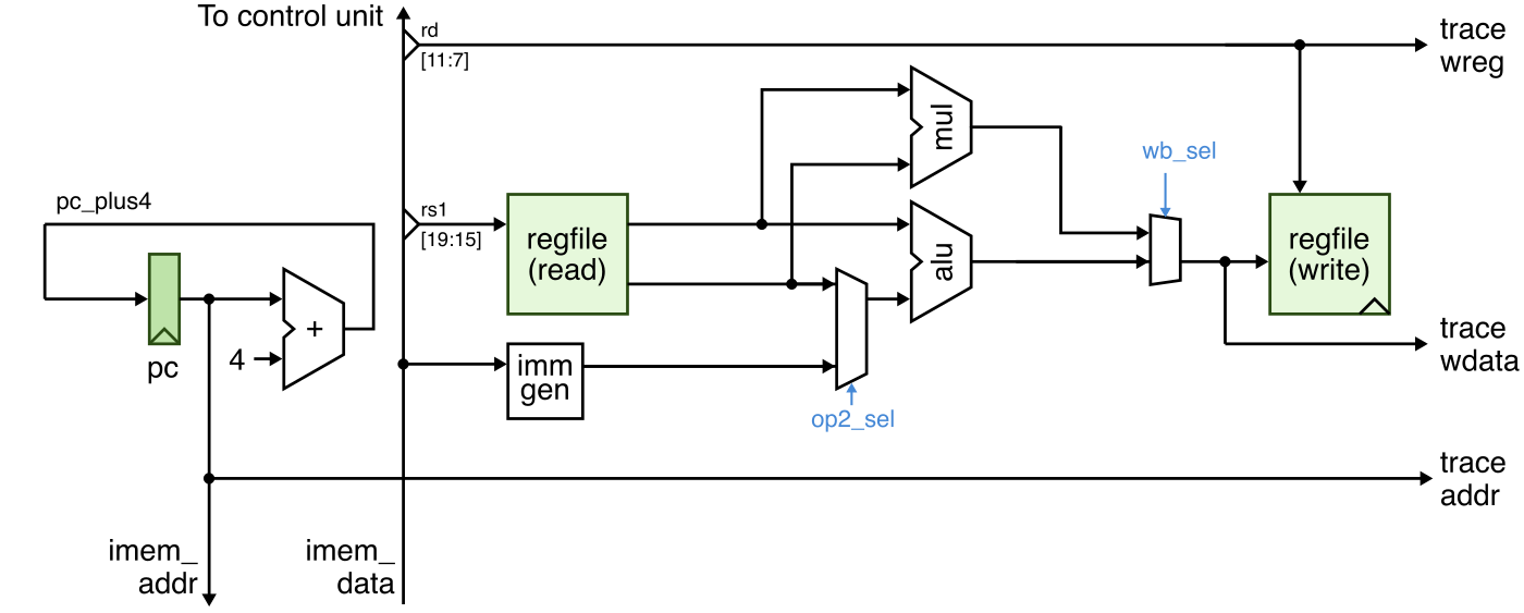
Notice this means we have a new control signal wb_sel. So we need to
add a new one-bit output port to ProcScycleCtrl named wb_sel and a
new one-bit input port to ProcScycleDpath named wb_sel (Step 2). We
also need to add a wb_sel signal to ProcScycle to connect these two
ports together (Step 3) like this:
// Control Signals (Control Unit -> Datapath)

logic op2_sel;
logic wb_sel;

// Status Signals (Datapath -> Control Unit)

logic [31:0] inst;

// Insantiate/Connect Datapath and Control Unit

ProcScycleDpath dpath
(
  .*
);

ProcScycleCtrl ctrl
(
  .*
);
The .* makes these top-level connections very simple! In the control
unit, we need to add a new column to the control signal table (Step 4)
and a new row for the MUL instruction (Step 5) like this:
  // Localparams for op2_sel control signal

  localparam rf  = 1'd0;
  localparam imm = 1'd1;

  // Localparams for wb_sel control signal

  localparam mul = 1'd0;
  localparam alu = 1'd1;

  // Task for setting control signals

  task automatic cs
  (
    input logic op2_sel_,
    input logic wb_sel_
  );
    op2_sel = op2_sel_;
    wb_sel  = wb_sel_;
  endtask

  // Control signal table

  always_comb begin
    casez ( inst )
                          //  op2  wb
                          //  sel  sel
      `TINYRV1_INST_ADDI: cs( imm, ??? );
      `TINYRV1_INST_ADD:  cs( rf,  ??? );
      `TINYRV1_INST_MUL:  cs( ???, ??? );
      default:            cs( 'x,  'x  );
    endcase
  end
Now we need to fill in the empty entries marked ??? with the correct
values (Step 6). We have created two new localparams (alu,mul) to
make it easier to understand the values in the control signal table.
Here is a figure that illustrates how the datapath and control unit fit together for the single-cycle RTL processor which supports ADDI, ADD, and MUL.

Finally, we must thoroughly test this instruction before moving on to the next instruction (Step 7). Go ahead and run the basic test case and your new directed test case on your updated single-cycle processor.
And let's zoom out to keep track of our progress.
Remember, you will need to add many more directed test cases for your final lab submission!
Discussion Check-Off Task 5: Verify Single-Cycle Processor
Show a peer student how your updated datapath and control unit correspond to the above block diagram. Then show a peer student your single-cycle processor passing all of the ADD, ADDI, and MUL test cases.
4. Clean Build
As a final step, do a clean build.
After your partner has finished their discussion you can get together and
copy any work you want from ece2300/sec10 into ece2300/groupXX to use
for your lab submission.